Most explanations of a vision marker stop at “the camera finds the part”. That is not enough to specify one, integrate one, or debug one. A useful understanding of an intelligent vision laser marking system breaks the process into five stages. Each stage carries its own error budget and its own share of the cycle time.
This guide walks through those five stages. It then shows where the milliseconds and the microns actually go. It is written for automation engineers, integrators and technical buyers who need numbers rather than marketing claims.
System architecture at a glance
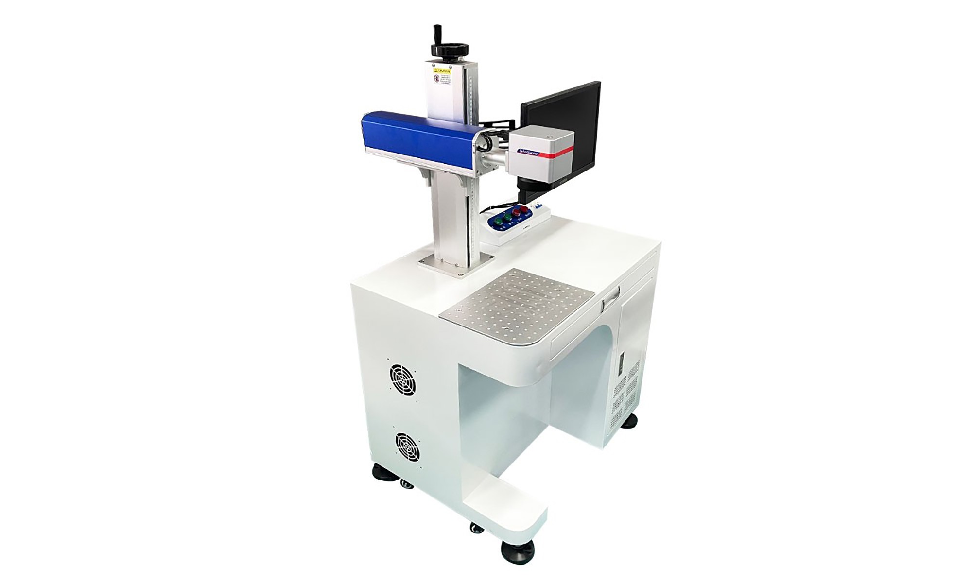
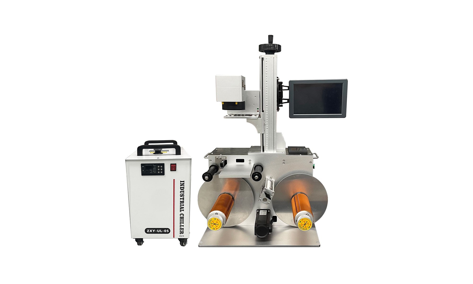
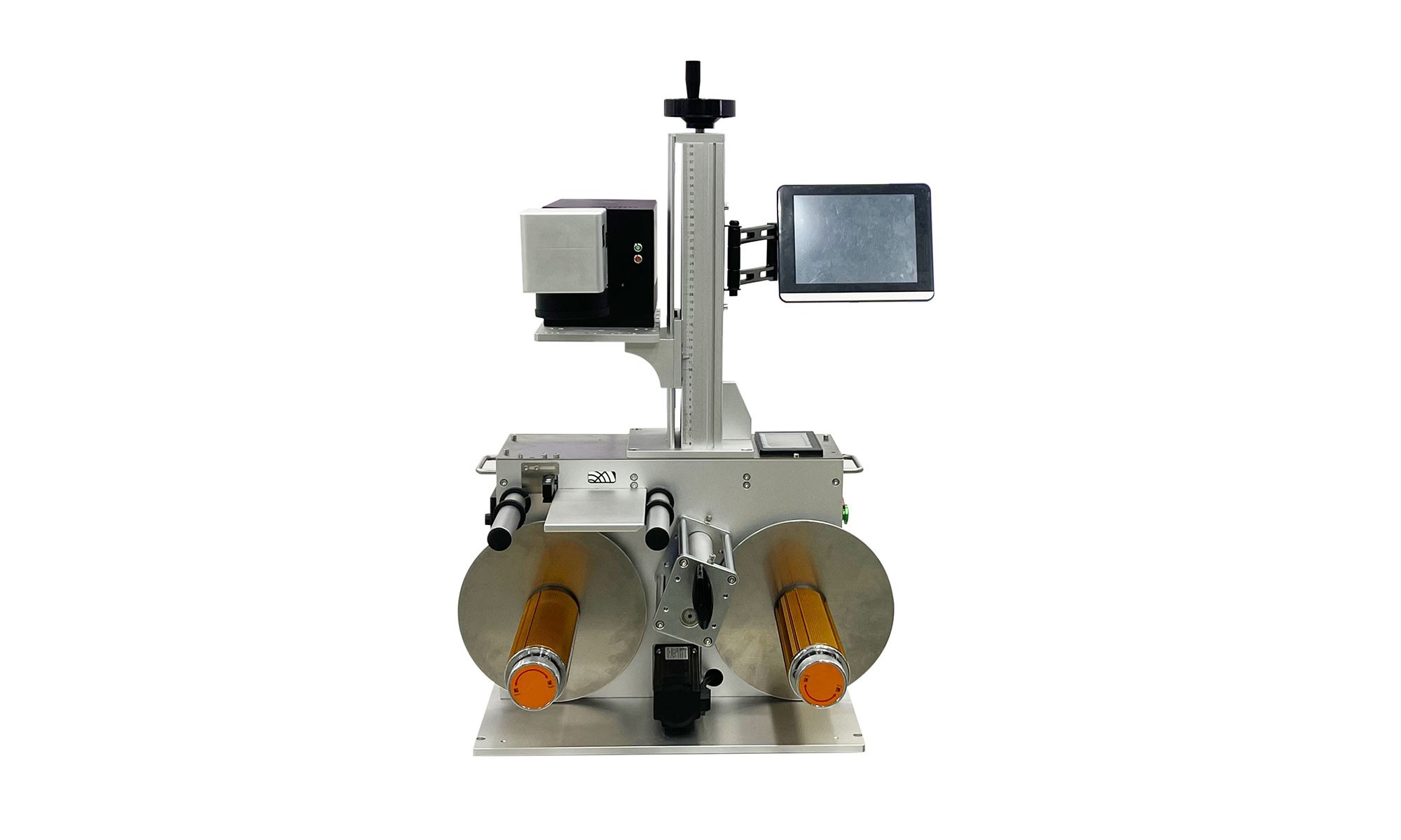
An intelligent vision laser marking system is built from four hardware blocks and one software layer:
- Imaging: camera, lens, illumination
- Positioning: XY stage, rotary axis or conveyor, with an optional Z axis
- Marking: fibre laser source, galvo scanner, F-theta lens
- Control: industrial PC, IO module, PLC handshake
- Software: vision module, marking module, and one shared coordinate frame
Everything else follows from a single design decision. Either the camera and the laser share the same optical axis, which is coaxial, or they sit side by side, which is off-axis. Coaxial designs avoid parallax error but cost more. Off-axis designs are cheaper and need careful calibration.
Stage 1: image capture
The camera fires when a trigger arrives, usually from a photoelectric sensor or the PLC. Exposure time, gain and illumination decide whether the image is usable.
Three choices matter most. First, resolution, because it sets the smallest feature the software can see. Second, the lens, because a telecentric lens removes perspective error on parts with height variation. Third, lighting, because contrast is what the algorithm actually consumes.
For shiny metal, a dome light or a low-angle ring light usually beats a bright diffuse panel. For dark plastic, backlighting gives the cleanest silhouette. In short, the lighting choice is a mechanical engineering decision, not an accessory.
Stage 2: feature extraction and pose estimation
The vision module preprocesses the image: noise removal, contrast enhancement, binarisation and edge detection. It then extracts the feature you defined, which may be a contour, a hole, a corner, a fiducial dot or a printed pattern.
Next, the algorithm matches that feature against a stored template and returns a pose, meaning an X offset, a Y offset and a rotation angle. Some systems also return a scale correction for thermal expansion.
This stage dominates the cycle time. A simple blob or edge match takes about 20 milliseconds. A robust contour match on a low-contrast surface can take 100 to 150 milliseconds. Therefore, ask a supplier which algorithm runs on your part, not which algorithm exists in the software.
Stage 3: coordinate transformation and calibration
The pose from the camera lives in pixel coordinates. The laser works in millimetres. Calibration is the map between the two.
A proper calibration moves a target through a grid of positions, measures the result with the camera, and solves for the transformation. Good practice uses at least 9 points across the full field, and 25 points for large fields.
Skip this step and everything downstream drifts. A poorly calibrated intelligent vision laser marking system can look correct in the centre of the field and be 0.3 mm out at the edges. That error is invisible in a demo and obvious in production.
Stage 4: galvo marking and dynamic focus
Once the layout is transformed, the galvo scanner steers the beam. Mirrors move in microseconds, which is why the scanner, not a motorised stage, does the marking.
On flat parts, a fixed F-theta lens is enough. On curved or stepped parts, a dynamic focus module moves the focus along Z while the scanner marks. This is the difference between a 2D system and a true 3D one.
Marking time depends on the vector length, the fill density and the material. A short serial number takes about 50 milliseconds. A filled 20 x 20 mm logo on stainless steel can take 400 milliseconds or more.
Stage 5: verification and closed feedback
After marking, the same camera often reads the mark back. It checks position, contrast and, in many cases, decodes the QR or Data Matrix code.
This verification step is what makes traceability defensible. If the code fails to decode, the system flags the part immediately instead of shipping a defect downstream.
Closed-loop correction goes one step further. The system compares the actual mark position with the target and adjusts the offset for the next part. Over a shift, this keeps accuracy stable as the machine warms up.
Accuracy, repeatability and the error budget
| Error source | Typical contribution | How to reduce it |
|---|---|---|
| Camera resolution | 20 – 50 µm | More pixels, smaller field of view |
| Lens distortion | 5 – 30 µm | Telecentric lens, full-field calibration |
| Calibration residual | 5 – 20 µm | More calibration points, thermal stability |
| Galvo non-linearity | 10 – 40 µm | Factory correction file, on-machine test grid |
| Part surface and contrast | 10 – 100 µm | Better lighting, stable nest |
| Thermal drift | 5 – 20 µm | Warm-up time, temperature compensation |
Read the table as a total, not as a list. In practice, the dominant term is usually part presentation, not the hardware. Fix the nest and the lighting before you upgrade the camera.
Cycle time: where the milliseconds go
| Step | Typical time |
|---|---|
| Image capture and exposure | 5 – 20 ms |
| Vision processing | 20 – 150 ms |
| Coordinate transform | under 5 ms |
| Laser marking | 50 – 500 ms |
| Verification and IO handshake | 10 – 50 ms |
| Total per part | 100 – 700 ms |
Throughput is therefore set by the vision step and the marking step together. If your takt time is 1.5 seconds, almost any configuration works. If it is 300 milliseconds, you need a fast algorithm and a short mark.
Integration: IO, PLC, MES and conveyors
An intelligent vision laser marking system rarely runs alone. It usually sits inside a cell with a conveyor, a robot or a pick-and-place unit, and it reports to a higher system.
Three interfaces decide how painful the integration is. First, a clean hardware handshake over digital IO, so the PLC knows when to send and when to release. Second, a data interface such as TCP/IP, Modbus TCP or OPC UA, so the marking content can change per unit. Third, a logging path to MES or a database, so every serial number is stored against its timestamp and result.
Ask for the interface list before purchase. Retrofitting OPC UA support later is far more expensive than specifying it now.
Maintenance and calibration schedule
- Daily: check the camera window and the field lens for dust, and confirm that the lighting is even
- Weekly: clean the field lens and camera window, and inspect the air filter
- Monthly: back up all recipes and verify calibration with a test grid
- Quarterly: re-run the full-field calibration and measure axis backlash
- Annually: replace the cooling filter and inspect cables and connectors
Calibration is not a one-time event. It shifts with temperature, mechanical wear and any change to the optics.
Common technical problems and fixes
Mark is offset by a constant amount. The calibration is stale. Re-run it.
Mark is correct in the centre and wrong at the edges. Lens distortion or an incomplete calibration grid. Use more points.
Vision fails on some parts. Contrast is marginal. Change the lighting angle or add a polarising filter.
Cycle time drifts upward. The vision search area is too large. Tighten the region of interest.
Codes fail to decode. The mark is either too shallow or too bright. Adjust power, frequency and speed together.
How to write a technical specification
A clear specification prevents most integration surprises. Write it before you compare vendors.
Cover five points:
- Required positioning accuracy and repeatability, in micrometres
- Field of view and the maximum part envelope
- Cycle time budget, split into vision time and marking time
- Interfaces, meaning IO signals, protocol and data logging
- Acceptance test method, and the parts used for it
Then describe the environment. Ambient light, vibration, temperature swing and dust shift real accuracy far more than the sensor does.
Finally, ask each vendor to sign off on the acceptance test. An intelligent vision laser marking system that passes a written test on your own parts is one you can trust in production.
Frequently asked questions
Does an intelligent vision laser marking system need a special PC?It needs a stable industrial PC with a frame grabber or a direct camera link, plus enough CPU for the vision algorithm. A consumer laptop is not a substitute.
How long does calibration take?A full-field calibration takes 20 to 40 minutes. A daily verification takes under 5 minutes.
Can the system mark parts at any angle?Yes, up to the rotation range the algorithm supports. Full 360-degree rotation is normal for flat parts.
Conclusion
An intelligent vision laser marking system is a pipeline, not a single device. Imaging, feature extraction, calibration, marking and verification each contribute error and time. If you need help running a feasibility test on your own parts, contact our vision system engineers for a free assessment.